Inspecting Sensor Feeds
In this exercise, you will learn more about how to graph and interpret sensor data from the Intel RTF Drone.
Measuring Translational Movement (Accelerometer)
The inertial measurement unit (IMU) on board the Intel RTF Drone has an accelerometer that can measure translational accelerations to relatively high precision. The following steps will show you how to access this data in QGroundControl.
From the QGroundControl top menu bar, select Analyze under Widgets.

In Analyze, enter ‘acc’ into the filter box.
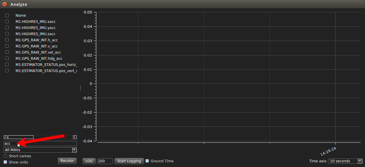
Select the check box for IMU.zacc, and verify that the resulting graph is close to -9.81 m/s^2 (gravity)
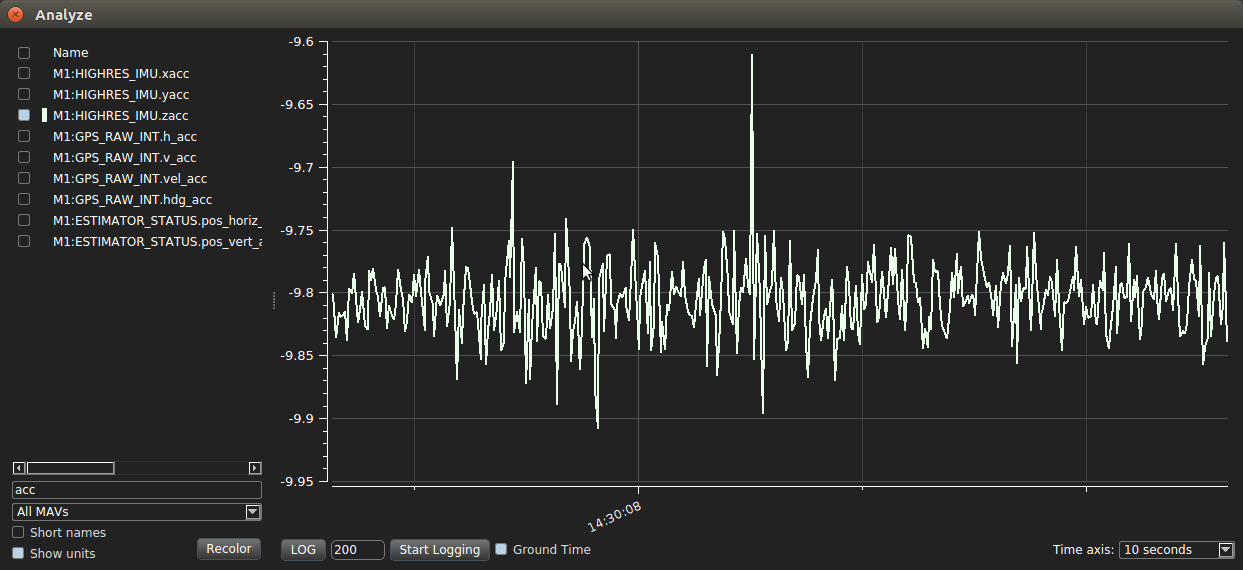
Now tap the table surrounding the drone and see if IMU.zacc changes. Try tapping underneath the drone from below the table. As you may notice, tapping the drone in the same plane as the drone will not cause large changes in IMU.zacc.
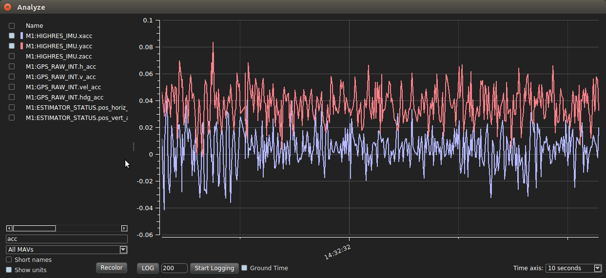
Deselect IMU.zacc and select IMU.xacc and IMU.yacc. Verify that the resulting graphs are close to zero. Now try those same taps with IMU.xacc and IMU.yacc. As you may have guessed, taps in the plane affect these values much more significantly than taps below or above the drone.
Measuring Angular Motion (Gyroscope)
In Analyze, select roll, pitch, and yaw by selecting them using the filter box.
First, try changing the yaw value by rotating the drone around the z axis (imagine a circle under the drone on the table, and rotate it around that circle.) The yaw value should cycle between pi/2 and negative pi/2.
Next, try rolling the drone by rotating it around the x axis (goes from the power button to the camera) and watching the roll value in Analyze.
Finally, try pitching the drone by rotating around the y axis (the one axis you haven’t tried yet, goes from one side of the drone to the other) and watching the pitch value change.
Trying out Optical Flow
Optical flow sensors help the drone estimate its current position by tracking features on the ground (you will learn more about the theory of optical flow later in the course.)
Here are the steps to activating optical flow on the drone. * Plug in the Teraranger USB cable to the drone USB port. Ask an instructor for help if need be. * SSH into the drone from the team laptop. Run the following commands
sudo systemctl start aero-teraranger.service
sudo systemctl start aero-optical-flow.service
Alternatively, you can run
cd ~/bwsi-uav/catkin_ws/src/aero-optical-flow/build
roscore &
sudo -E aero-optical-flow &
systemctl start aero-teraranger.service
Now return to QGroundControl on the laptop. Open
Widgets > MAVLink Inspector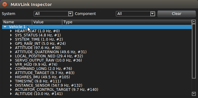
Scroll to OPTICAL_FLOW_RAD, and expand it. Make sure the quality is > 100 (hold the drone over a textured surface to increase quality).
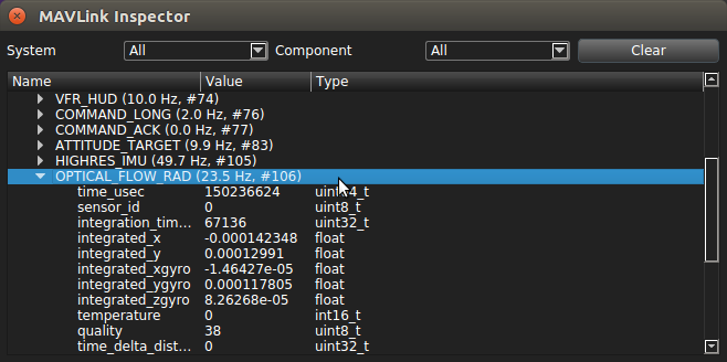
Now go to LOCAL_POSITION_NED, and expand it.
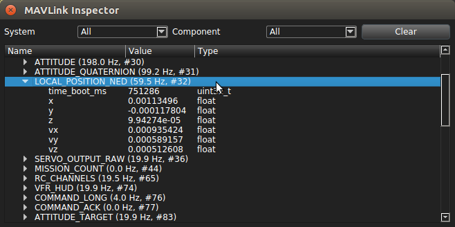
If you move the drone over a textured surface, you’ll be able to see the position estimate of the drone changing as new information comes in from the optical flow sensor, distance sensor, and IMU.
This is how the drone stabilizes itself in position control mode. It tries to maintain whatever initial position it reads, and RC control inputs modify that set position, causing the drone to center itself on a new point.
[ ]: