Calibrating Intel RTF Drones
Step 1: Connect to the Drone
You can connect the drone over QGroundControl using the following steps:
Connecting with QGroundControl
In order to connect the groundstation software (i.e. QGroundControl) to the drone via a router: (skippable if already completed)
On the drone:
Open a terminal and run
ifconfigGet the IP address of the drone which is labeled
inet addrunder thewlp1s0heading
On the groundstation:
Open QGroundControl
In the top left click on the “Q”
Select the “Comm Links” tap
Select “Add”
Set the “Type” to TCP
Set “Serial Port” to the IP address of the drone
Set “TCP Port” to 5760
Select “OK”
Select the new link and press “Connect”. This will connect QGroundControl to the drone
Alternative method: (if an instructor has provided you with a hostname for the drone you are calibrating)
Open QGroundControl
In the top left click on the “Q”
Select the “Comm Links” tap
Select “Add”
Set the “Type” to TCP
Set “Serial Port” to the hostname (_.beaver.works) of the drone
Set “TCP Port” to 5760
Select “OK”
Select the new link and press “Connect”. This will connect QGroundControl to the drone
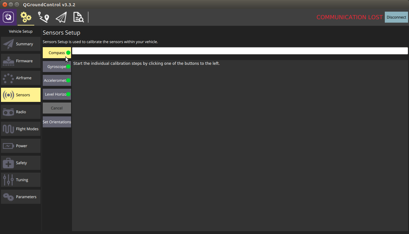
Step 2: Calibration Setup
Open QGroundControl and select Sensors from the side menu.
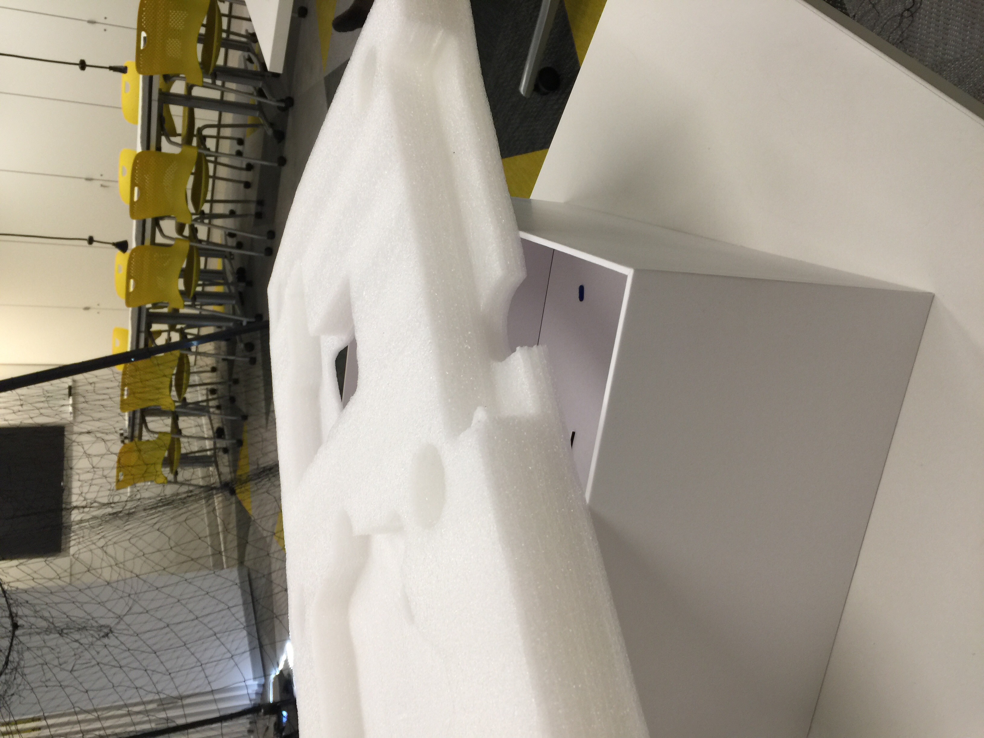
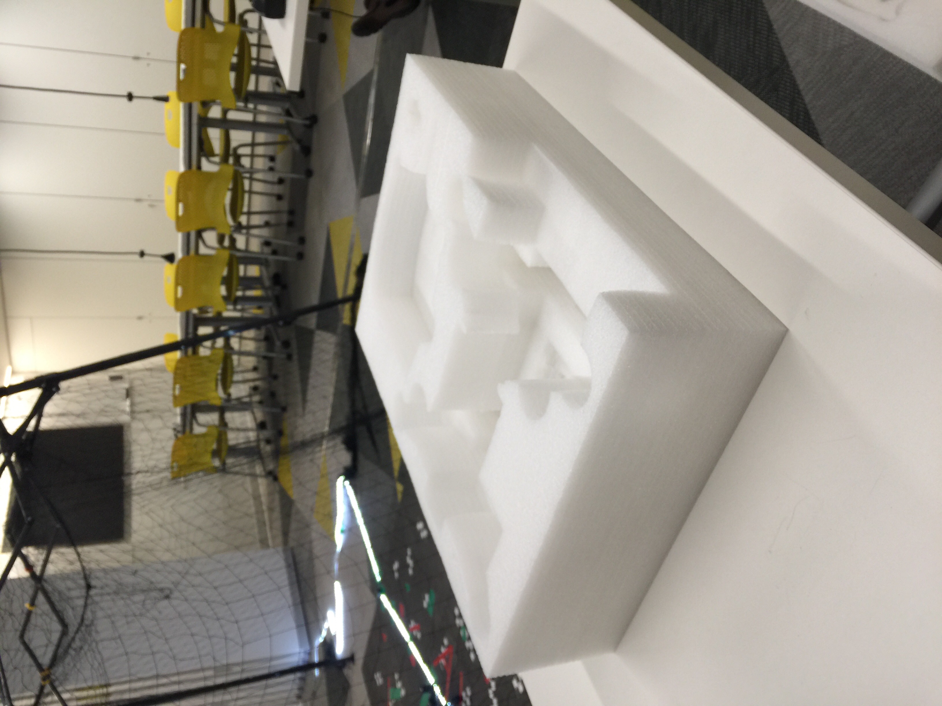
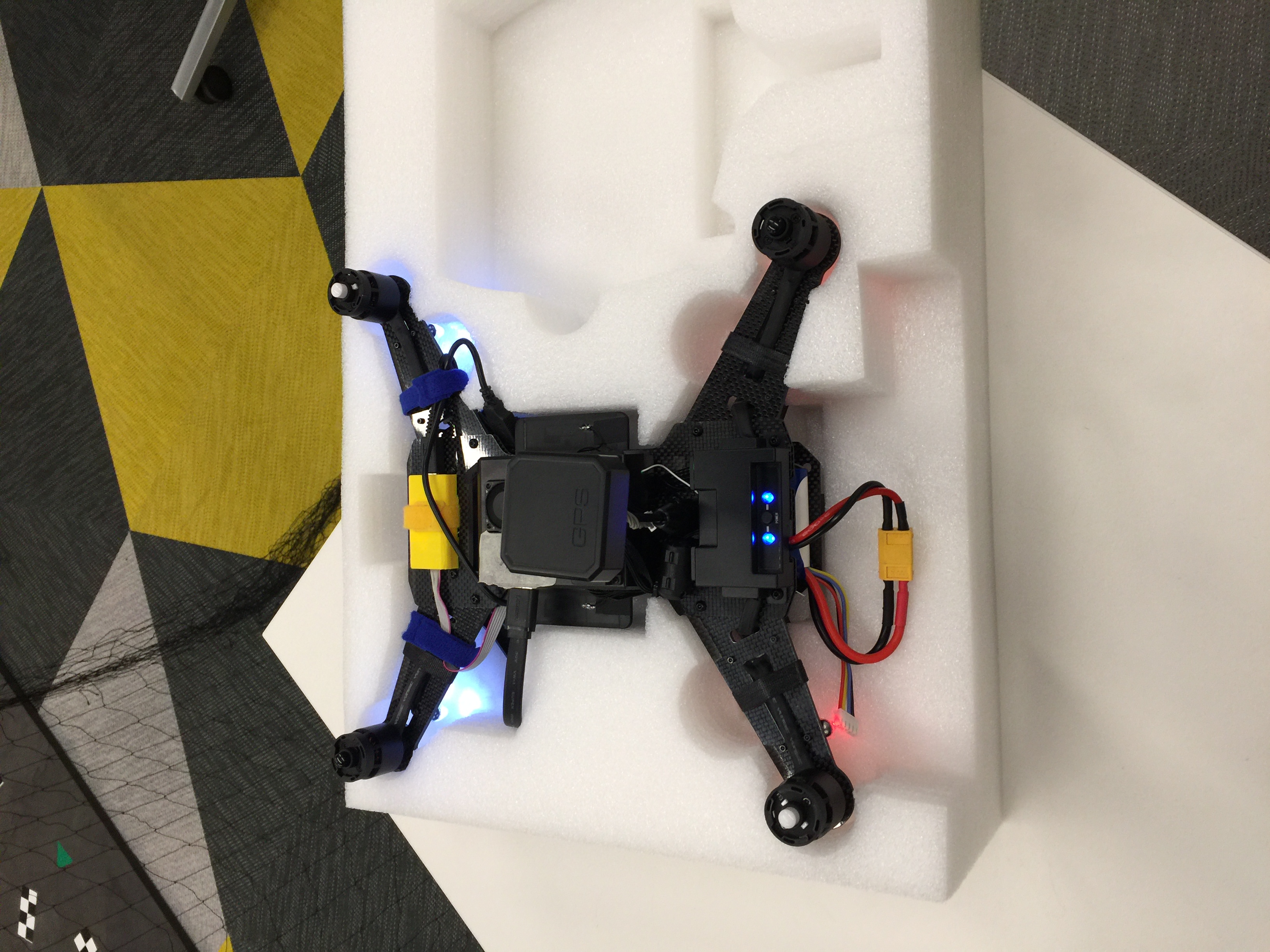
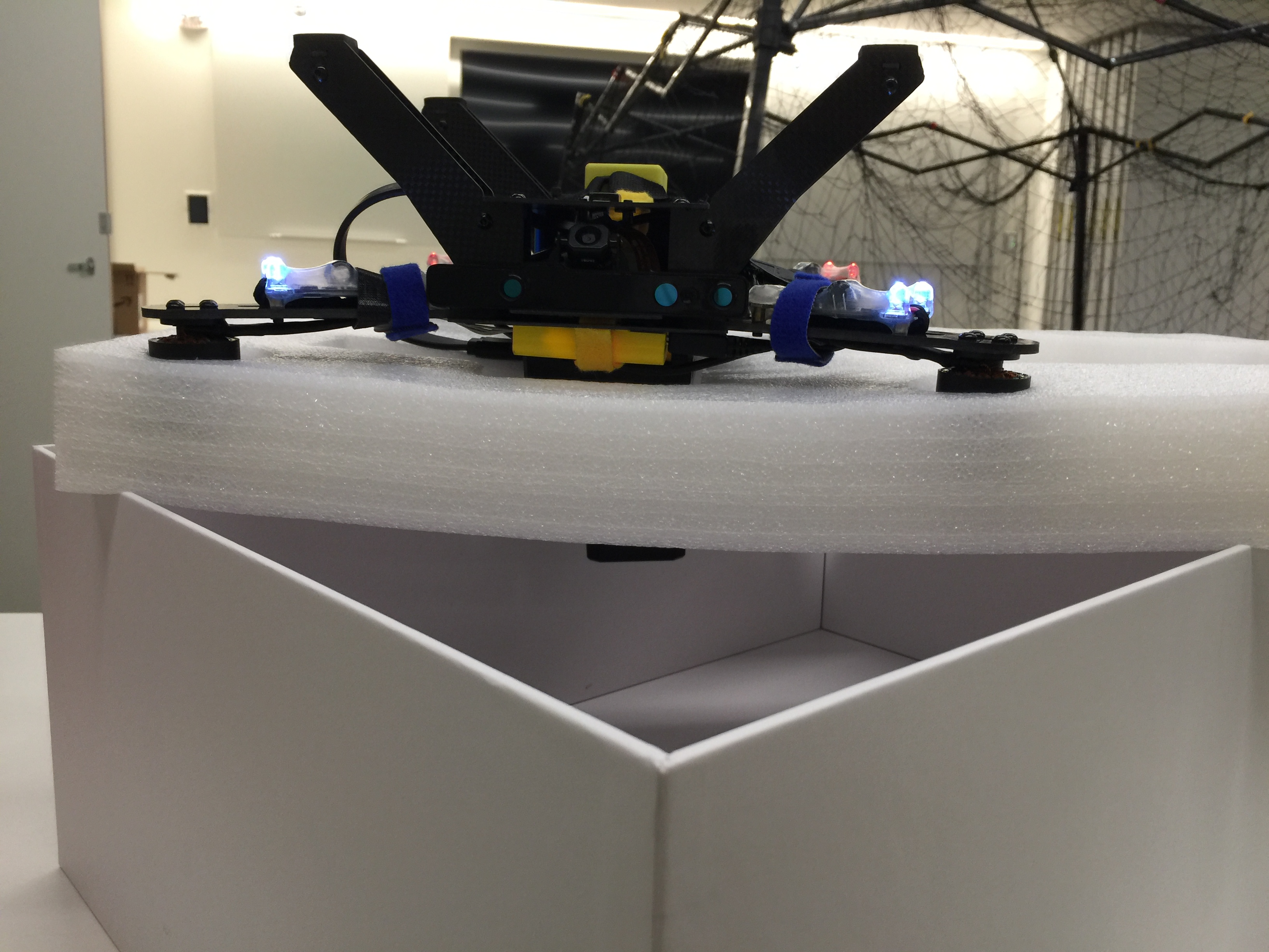
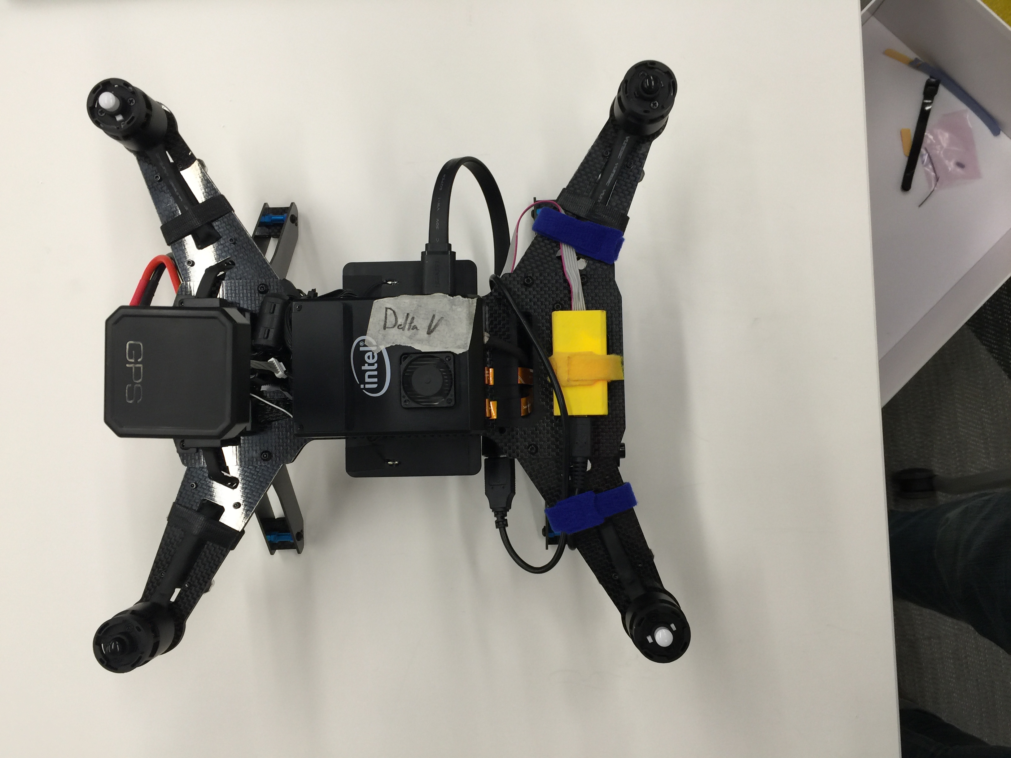
Ensure you have a box/upside-down mount and a regular mount as pictured below, as well as an Intel RTF Drone with a charged battery.
|
|
Step 3: Compass Calibration
Begin with the drone in the standard mount.
Select the Compass option in the calibration menu.
Select Ok when prompted.
Place the drone into each of the positions indicated in QGroundControl
Once the bounding box for each position turns yellow, rotate the mount continuously around the fixed point at which calibration started, until the bounding box turns green.
The compass calibration process (except the upside down configuration) is shown below.
For the upside-down configuration, place the drone in the box mount.

Turn the box mount continuously until the bounding box for the upside down configuration turns green.
Step 4: Accelerometer Calibration
Start with the drone in the standard mount.
Select Accelerometer from the left menu on the Sensors page in QGroundControl.
Move the drone to each of the indicated positions, and make sure to hold the mount still while the bounding box of each position is yellow in QGroundControl.
The accelerometer calibration process (except the upside-down configuration) is shown below.
For the upside-down configuration, place the drone in the box mount, as shown above in Step 3, and hold the box still until the bounding box on screen turns green.
Step 5: Gyroscope and Level Horizon Calibration
Both of these calibrations require the drone to be placed on a flat surface (without any mounts or other accessories).
Select Gyroscope from the left menu on the Sensors page in QGroundControl.
Wait for the bounding box to turn green. Gyroscope calibration is now complete.
Select Level Horizon from the left menu on the Sensors page in QGroundControl.
Wait for the progress bar at the top of the screen to fill. Level Horizon sensor calibration is now complete.
Note: Level Horizon calibration is critical for proper drone operation.
Make sure your flat surface is actually flat, and avoid moving anything on the surface while calibrating.
Step 6: Verifying Calibration
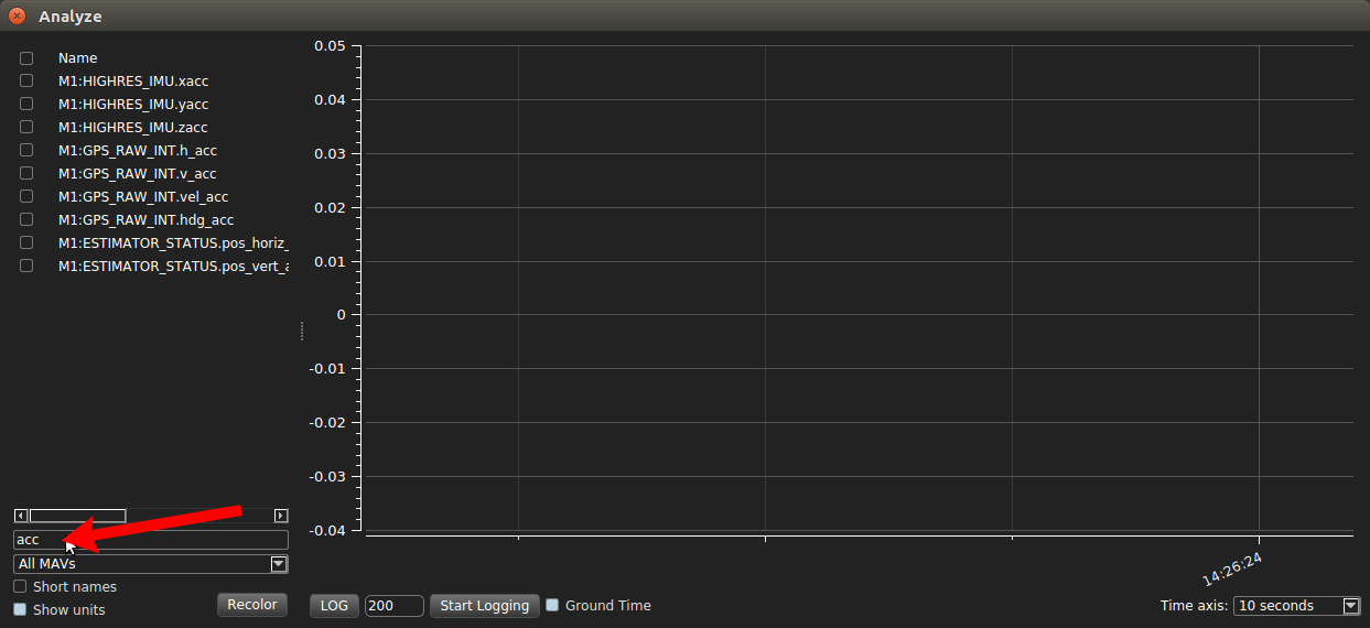
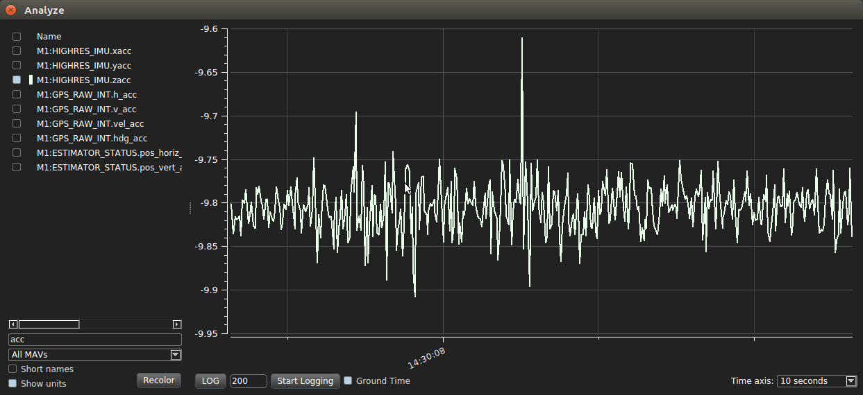
From the QGroundControl top menu bar, select Analyze under Widgets.

In Analyze, enter ‘acc’ into the filter box.
Select the check box for IMU.zacc, and verify that the resulting graph is close to -9.81 m/s^2 (gravity)
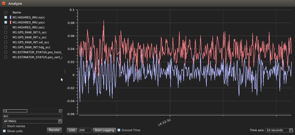
Deselect IMU.zacc and select IMU.xacc and IMU.yacc. Verify that the resulting graphs are close to zero. The drone is still flyable if the magnitudes of xacc and yacc deviate from 0 by less than 0.1 m/s^2.
Step 7: Radio Calibration (RC Controller)
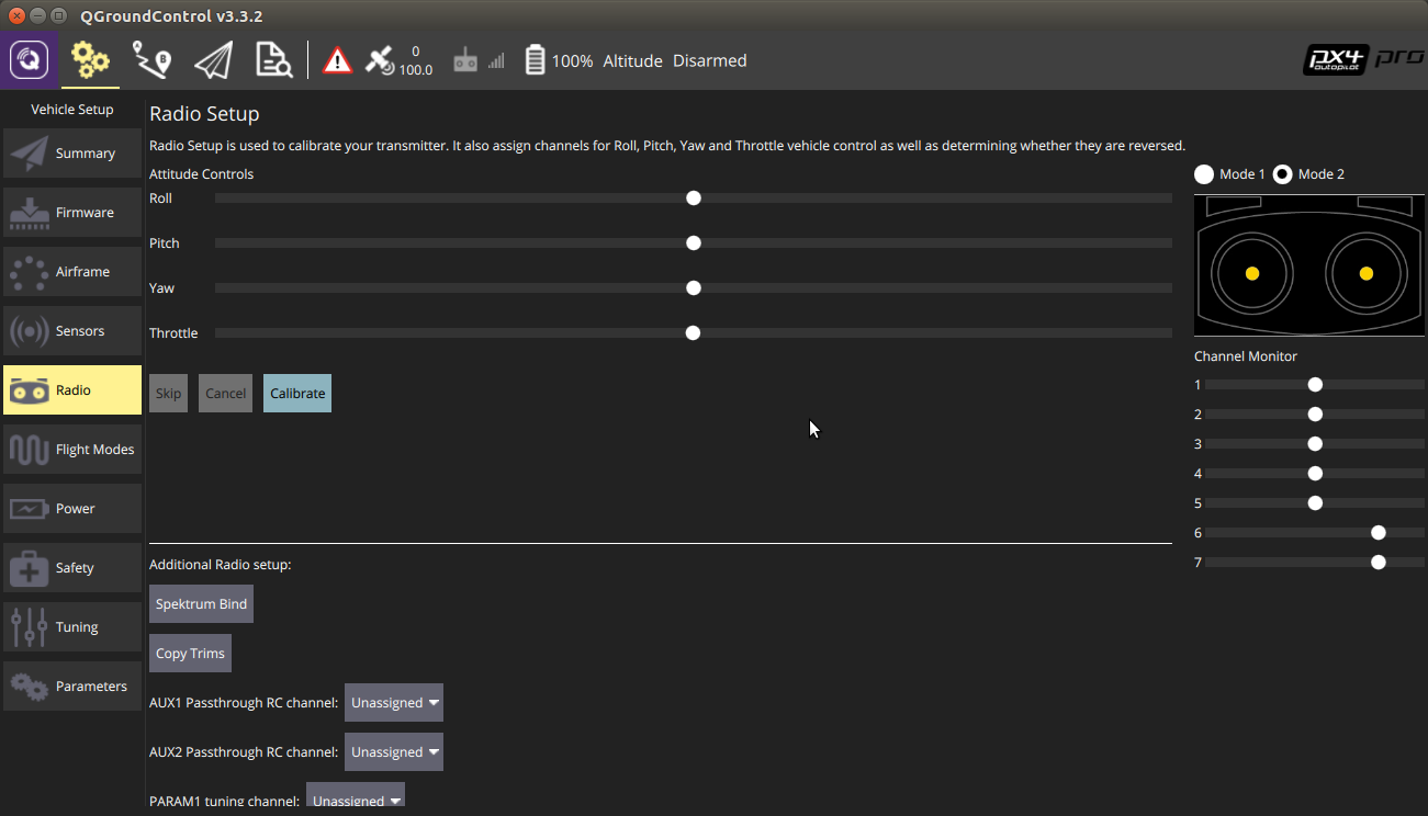
Obtain the radio paired to your drone and select Radio from the left-most menu in QGroundControl.
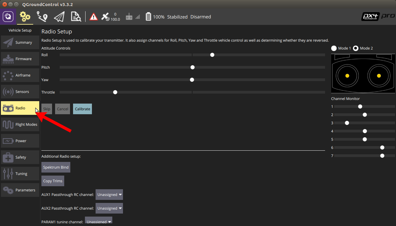
You will now zero the roll, pitch, yaw, and throttle. If the throttle is very low, as seen above, flip the “ARM/DISARM” switch to ARM.
Control surfaces pre-zeroing. (Your setup may vary)

Trims, labeled on the radio.
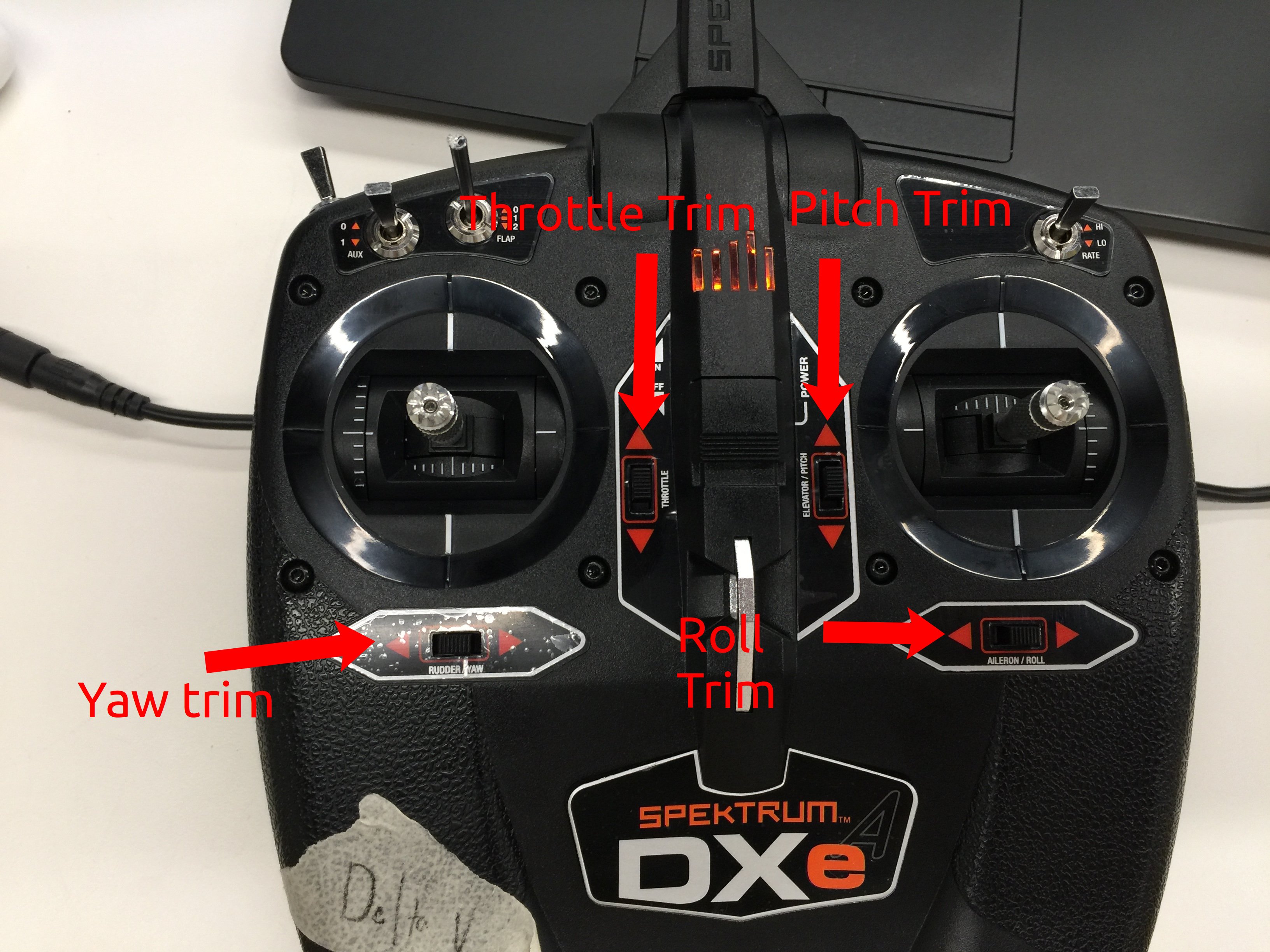
Ensure that both joysticks are centered as seen above, and then adjust the trims until the throttle, yaw, roll, and pitch are at the center of their sliders in QGroundControl.
Select ‘Calibrate’ on the Radio screen in QGroundControl, and then select OK when prompted (because you just zeroed your trims/subtrims.)
Follow the directions on screen for manipulating the joysticks. QGroundControl will detect the movement and continue through the calibration automatically.
Note: You can ignore the direction to play with transmitter switches.
Select OK to write the calibrated radio settings to your drone.
Flight Modes
To ensure everyone’s remote controls behave the same and that we can enter the appropriate flight modes for our test, we need set the flight modes. Flight mode is controlled by the toggle on the upper left shoulder of the remote control which is labeled “FLIGHT MODE”. This toggle is mapped to the onboard flight controller using QGroundControl’s “Flight Mode” tab. In the Flight Mode tab in QGC, set:
Mode channel: Channel 5
Flight Mode 1: Manual
Flight Mode 4: Position
Flight Mode 6: Offboard
Leave all other options as Unassigned
You are now finished with calibration!
[ ]: